INTRODUCTION
Internal plate fixation and intramedullary nailing are long-standing methods to provide fixation of fractures of the femoral and humeral shaft.1,2 These techniques are also used for fracture non-unions, osteotomy and bulk allograft stabilization.1,2 Internal fixation needs to provide enough rigidity, compression, and have adequate durability (fatigue life) to promote bone healing.2,3 Intramedullary rods are implanted along the axis of the center of mass and provide better durability than plates, but are not as rigid.4 Implanted metal plates are fixed to cortical bone with screws, and can provide compression and better rigidity under conditions of good bone contact. The differences between these two fixation methods have different biomechanical and clinical outcome considerations.1,2,3,4,5 Intramedullary rods have become the preferred clinical choice for femoral shaft non-union.2,3 A rod with improved durability might be useful for situations with prolonged healing such as bulk allografts, and severe bone defects as is seen with high-energy trauma and metastatic bone disease. Intramedullary rods are typically metal and are traditionally a fixed size that stabilizes the fracture by using distal and proximal crosslocking screws.3,4,6 A recently developed Intramedullary system (IS) that utilizes a photodynamic monomer offers the potential to completely fill the intramedullary canal and provide better stabilization of a fracture or an osteotomy.7,8 The implantation process begins with clearance of the soft tissue of the medullary canal by a flexible, cannulated, drill bit guided by a wire.7,8 An angioplasty-like balloon adapted for this system is then inserted down the canal and filled with a liquid photodynamic monomer until the balloon is expanded and conforms to the inner cortical walls.7,8 Finally, an optical fiber inserted down the cannulated balloon delivers visible blue light (436 nm) to polymerize the liquid monomer and thus hardening the implant.7,8 Each implant is expandable to ensure a conformal fit between the implant and the canal and could potentially offer improved biomechanics. This technology has shown promising results in a large animal model and in clinical use.9,10,11 As a first step in evaluating the mechanical properties of this new rod, we compared the following biomechanical properties of three IS diameter sizes to a locking compression plate appropriately sized for either the humerus osteotomy or femur osteotomy model. For the humerus, three IS diameter sizes (11 mm, 13 mm, 15 mm) were compared to a 3.5 mm Locking Compression Plate (LCP) and screw system.12,13 For the femur, three IS diameter sizes (13 mm, 15 mm, 17 mm) were compared to a 4.5 mm Locking Compression Plate (LCP) and screw system.7,8,9 Using a bone surrogate model we evaluated these implants using biomechanical parameters: stiffness, yield load, peak load, yield displacement, peak displacement, and finally cycles to failure under axial load.5,6,7,8,9,10,14 In both models, previous biomechanical testing of plates and intramedullary rods provided a suitable predicate.1,4,5,10,12,13,14,15,16,17,18,19,20 An osteotomy model was chosen for both models because of the biomechanical demand such a defect places on a fixation system.5 Understanding the biomechanical performance of these two implant systems could be beneficial in directing clinical decisions when the two systems might be considered for the same indication.
MATERIALS AND METHODS
Humerus Osteotomy
Humerus Experimental Groups: The static and dynamic mechanical properties of three different diameter IS implants and an LCP implant were compared in four humerus experimental groups: (1) 11 mm, (2) 13 mm, (3) 15 mm diameter IS implants (IlluminOss Medical, East Providence, RI, USA), and (4) 3.5 mm titanium Locking Compression Plate (LCP) (7 hole, 98 mmx11 mm) with 3.5×30 mm titanium locking screws (Synthes, Westchester, PA, USA). Six constructs per group were built and tested for the static parameters and an additional three constructs per treatment group were built for the dynamic testing.
Humerus Model and Fabrication of Constructs: A synthetic humerus bone model (Sawbones Product #3404 – Sawbones, Vashon, WA, USA), which has been shown to exhibit similar mechanical properties to bone, was cut at the midpoint with an additional 5 mm removed from the cut ends to create a 10 mm defect.16,17 The remaining segments of the synthetic bone were removed 95 mm away from the center cut. A custom-made jig was built to hold both sections of the synthetic bone while a drill press was used to widen the intramedullary canal to the final diameter (11 mm, 13 mm, 15 mm). Synthetic bone constructs were assembled with a 10 mm spacer inserted at the midline to preserve the spacing and alignment (Figure 1).
Figure 1: Dimensions for the IS construct A) femur and D) humerus, respectively. Dimensions for LCP construct B) femur and E) humerus, respectively. Picture of final construct in the sawbones C) femur and F) humerus, respectively.
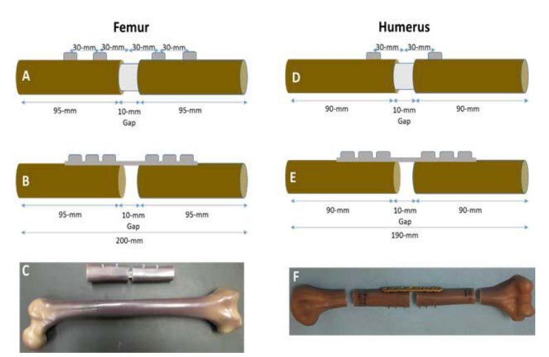
For the humerus IS implants, a 180 mm long deflated and wrapped polyethylene terephthalate (the material used in Dacron® fiber) balloon with either an 11 mm, 13 mm, or 15 mm diameter was inserted down the intramedullary canal and filled with liquid monomer. The monomer was polymerized for 500, 600, and 700 seconds for the 11 mm, 13 mm and 15 mm balloons, respectively using 436 nm visible light delivered by an optical fiber (Figure 2). The hardened, polymerized IS was further secured in the construct by two 3.5×28 mm self-tapping screws (DSS, Inc. Fresno, CA, USA) into pre-drilled pilot holes 30 mm from the center of the construct on either side of the osteotomy.
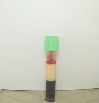
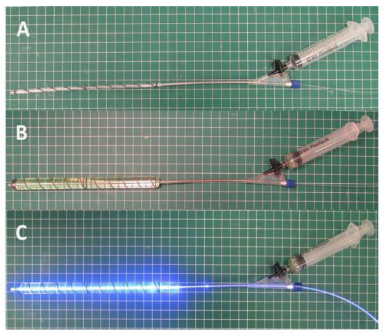
Figure 2: Fabrication of expandable photodynamic intramedullary system (IS). A: angioplasty-like balloon connected to syringe and light fiber. B: injection of photodynamic monomer to expand the angioplasty-like balloon. C: polymerization and hardening of photodynamic monomer by 436 nm visible light delivered by an optical fiber.
The LCP construct was prepared using the same custom jig as the IS construct. After cutting to the proper length, the plate was aligned on the lateral aspect of the synthetic bone and pilot holes were pre-drilled. Six 3.5×30 mm titanium locking screws were screwed into the plate by hand. The middle hole on the 7 hole LCP was left open above the osteotomy.
Humerus Cantilever Bend Mechanical Testing: All static and dynamic testing was performed using ASTM F382-99 as a nominal guide (Standard Specification and Test Method for Metallic Bone Plates).14,18 For static testing, each construct was loaded in custom fixtures that allowed unrestricted bending when subjected to a transverse compressive load in the anterior to posterior direction (Figure 3A). All testing was completed in a servo-hydraulic materials testing machine (Instron 8521S, Instron, Norwood, MA). All specimens were loaded at a rate of 25.4 mm/ min and the test was stopped before the humerus constructs were deflected beyond a functional limit (>30 mm).
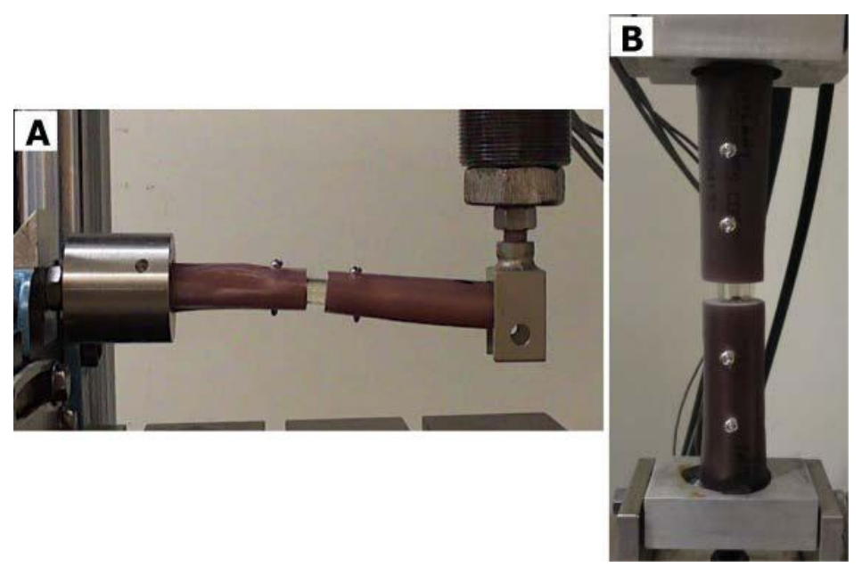
Figure 3: Picture of IS construct in the A) humerus model in the cantilever bend test and the B) femur model in the compressive axial load test in mechanical testing frame.
For dynamic testing, the same custom fixtures as static testing were used to apply a cyclic sinusoidal compressive load along the transverse axis of the humerus (anterior to posterior direction) at a rate of 5 Hz (MTS model 810, MTS Corp., Eden Prairie, MN, USA). Three samples were tested at each of the three loading conditions (33N, 66N, 99N) with an R ratio of 10 for 1,000,000 cycles or until the construct was permanently deformed (10 mm total displacement). Samples that completed 1,000,000 cycles without being permanently deformed in a given loading condition were then stepped up to the next loading condition for additional 1,000,000 cycles until the final loading condition (99N) was complete. The loading conditions were determined from in vivo reports of a 120° bending moment on the humerus during Activities of Daily Living (ADLs).19,20 To achieve a bending moment of 4.6 nm seen on the humerus during ADLs, the minimum load of 33 N was applied with a moment arm of 140 mm. The additional loading conditions (66 and 99 N) were included to encompass three factors beyond typical ADLs. For the 3.5 mm plate constructs, the orientation of the plate was antero-medial. After dynamic testing, the constructs were visually inspected for defects.
Femur Osteotomy
Femur Experimental Groups: For the femur model, the biomechanical properties of four experimental groups were evaluated: (1) 13 mm, (2) 15 mm, (3) 17 mm diameter IS implants (IlluminOss Medical, East Providence, RI, USA), and (4) PERI-LOC 4.5 mm Locking Compression Plate (LCP) (Smith and Nephew, 8-hole, 4.5 mm × 157 mm, stainless steel, Part #71809308) with six 4.5×40 mm PERI-LOC self-tapping cortex screws and two locking buttons (Smith and Nephew, Memphis, TN, USA Part#3826040). Three constructs per IS group were built and compared to six LCP samples previously tested in Tompkins et al.15
Femur Model and Fabrication of Constructs: A synthetic femur bone model (Sawbones Product #3403 – Sawbones, Vashon, WA, USA), which has been shown to exhibit similar mechanical properties to bone, was cut at the midpoint with an additional 5 mm removed from the cut ends to create a 10 mm defect.9,21 A large femur model was used for the 17 mm IS and LCP groups, whereas a medium femur model was used for the 15 mm and 13 mm IS groups. The femur model sizes were chosen to accommodate the relative size of the large diameter (17 mm) IS and LCP constructs. The remaining segments of the synthetic bone were removed 100 mm away from the center cut. Similar to the humerus model, a custom-made jig was built to hold both sections of the synthetic bone while a drill press was used to widen the intramedullary canal to the final diameter (13 mm, 15 mm, 17 mm). Synthetic bone constructs were assembled with a 10 mm spacer inserted at the midline to preserve the spacing and alignment.
For the IS implants, a 180 mm long deflated and wrapped polyethylene terephthalate (the material used in Dacron® fiber) balloon with either an 13 mm, 15 mm, or 17 mm diameter was inserted down the intramedullary canal and filled with liquid monomer. The monomer was polymerized for 600, 700, and 800 seconds for the 13 mm, 15 mm and 17 mm balloons, respectively using 436 nm visible light delivered by an optical fiber (Figure 2). The hardened, polymerized IS was further secured in the construct by a total of four 3.5×40 mm selftapping large cortical screws (Part#204840 Diverse Surgical Solutions, Fresno, CA, USA) drilled 30 mm and 60 mm from the center of the construct on either side of the simulated osteotomy.
The LCP constructs were prepared using the same custom jig as the IS construct. However, after cutting to the proper length, the intramedullary canal was filled with polymethylmethacrylate (PMMA) bone cement to increase the purchase of the screws. The plate was aligned on the lateral aspect of the synthetic bone and pilot holes were drilled. Six 4.5×40 mm large, cortex, self-tapping screws were screwed into the plate by hand (tightened to a torque of 35 inch-pounds). The two middle holes on the 8-hole LCP were filled with locking buttons which have been shown to improve the fatigue life.15
Femur Axial Compression Mechanical Testing: All static and dynamic testing was performed using ASTM F382-99 as a nominal guide (Standard Specification and Test Method for Metallic Bone Plates).15,22 For static testing, each construct was loaded in custom fixtures that allowed unrestricted bending when subjected to a compressive axial load. All biomechanical testing was completed in a servo-hydraulic materials testing machine (Instron 8521S, Instron, Norwood, MA, USA). All specimens were loaded in axial compression at a rate of 25.4 mm/min and the test was stopped before the femur constructs were deflected beyond a functional limit (>30 mm) (Figure 3B).
For dynamic testing, the same custom fixtures used for static testing were used to apply a cyclic sinusoidal compressive axial load at a rate of 5 Hz (MTS model 810, MTS Corp., Eden Prairie, MN, USA). Samples were tested at each of the three loading conditions (689 N, 798 N, 900 N) with an R ratio of 10 for 1,000,000 cycles or until the construct was permanently deformed (10 mm total displacement). Samples that completed 1,000,000 cycles without being permanently deformed in a given loading condition were then stepped up to the next loading condition for additional 1,000,000 cycles until the final loading condition (900 N) was complete. The loading conditions were determined from published reports on the number of cycles equivalent to one year of walking.23 The applied load parameters were determined from previously published mechanical testing data (yield load 1060 N) of a plate and compression screw construct test using similar methods (quasi-static compression. 65%, 75%, and ultimately 85% (698 N, 798 N, 900 N) of yield load was applied to simulate three patients of varying weight (70 kg, 81 kg, and 92 kg) standing on one leg with an implant.15 The dynamic testing was performed on the femur IS constructs and compared to previously tested and published specimens from Tompkins et al.15
Statistical Analysis
Differences in biomechanical parameters between interventions (stiffness, yield load, peak load, yield displacement, peak displacement, and cycles to failure) were tested statistically using a one-way analysis of variance (ANOVA) with a Tukey’s multiple comparisons test to evaluate differences between treatment groups for the humerus (11 mm, 13 mm, 15 mm IS, and LCP) and the femur seperately (13 mm, 15 mm, 17 mm IS, and LCP) (GraphPad Prism, La Jolla, CA, USA). In all cases, statistical significance was set to p<0.05 a priori. Treatment group sample sizes were estimated based on previously published reports of static and dynamic testing of locking plates and pilot testing.15,24
RESULTS
Humerus Osteotomy
Humerus Stiffness: The 15 mm IS construct group had the highest average stiffness (15 mm IS 11.67 N/mm, SD 1.280; LCP – 9.983 N/mm, SD 2.26; 13 mm IS 7.367 N/mm, SD 1.299; 11 mm IS 4.617, SD 0.4309) (Figure 4A). There was a significant difference in stiffness between the treatment groups (F=26.50, p value=<0.0001). The 15 mm IS construct was not significantly different from the plate LCP construct (Dunnet’s Multiple Comparisons Test, Mean Diff=1.683 N/mm; p value=0.1468). The 13 mm and 11 mm IS constructs were significantly less stiff than the plate construct (13 mm vs. Plate, Mean Diff=-2.617, p value=0.0155; 11 mm vs. Plate, Mean Diff=-5.367, p value=<0.0001).
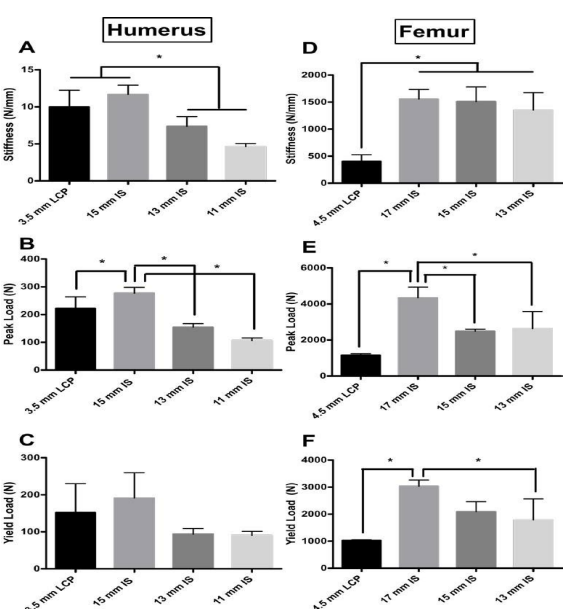
Figure 4: Stiffness (N/mm) of the four treatment groups for the A) humerus and D) femur model. For the A) humerus model, a non-significant difference was found between the 3.5 mm plate and the 15 mm IS construct. Also for the humerus model a significant difference was found between the 15 mm IS and LCP constructs and the 13 mm and 11 mm IS constructs. For the D) femur model, a non significant difference was found between the 17 mm, 15 mm, and 13 mm IS constructs. Also in the femur model, a significant difference was found between the 17 mm, 15 mm, 13 mm IS and LCP constructs (p value<0.05). Peak load (N) for the four treatment groups for the B) humerus and E) femur model. The 17 mm IS construct had significantly greater peak load than the other experimental groups for both the B) humerus and E) femur models. Yield load (N) of the four treatment groups for the C) humerus and F) femur model. In the femur model B3), a significant difference (indicated by asterisk) in yield was observed between the 17 mm IS group and the LCP and 13 mm IS group (p value<0.05). Asterisk indicates a significant difference between groups.
Humerus Peak and Yield Load: The 15 mm IS construct group had the highest average peak and yield load (276.8 N, SD 21.05; 191.4 N, SD 68.15 respectively) (Figure 4B and 4C, respectively). There was a significant difference in peak and yield load between the groups (F=56.22, p value=<0.0001; F=5.135, p value=0.0085 respectively). The 15 mm IS construct had a significantly larger peak load when compared to all experimental groups (Dunnet’s Multiple Comparisons Test, Mean Diff =54.10 N; p value=0.0029) (Figure 4B). The 15 mm IS construct also had the highest yield load, but there were no significant differences in yield load between the IS experimental groups and the LCP group (15 mm IS vs. LCP, Mean Diff=39.5 N, p value=0.4407; 13 mm IS vs. LCP, Mean Diff=-58.35 N, p value=0.1657; 11 mm IS vs. LCP, Mean Diff=-61.42, p value=0.1381) (Figure 4C).
Humerus Peak and Yield Displacement: The 15 mm IS construct had the highest peak and yield displacement (17.87 mm and 31.90, respectively) of the construct groups (Figure 5A and 5B). There was no significant difference between the any of the IS constructs and the LCP group for either peak or yield displacement (Peak Displacement, 15 mm IS vs. LCP, Mean Diff=1.733 N, p value=0.9422; 13 mm IS vs. LCP, Mean Diff=- 2.283 N, p value=0.8821; 11 mm IS vs. LCP, Mean Diff=4.3, pvalue=0.5536; Yield Displacement, 15 mm IS vs. LCP, Mean Diff=0.9833 N, p value=0.9842; 13 mm IS vs. LCP, Mean Diff=- 3.983 N, p value=0.5349; 11 mm IS vs. LCP, Mean Diff=-2.0, p value=0.8908) (Figure 5A and 5B).
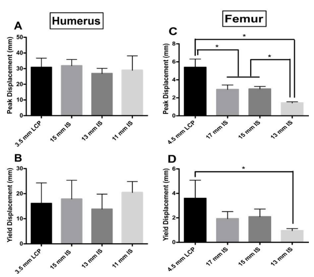
Figure 5: Peak displacement (mm) for the four experimental groups for both the A) humerus and C) femur models. Yield displacement (mm) for the four experimental groups for both the B) humerus and D) femur models. For the A) humerus group, no significant difference was observed for peak displacement between groups. Also for the B) humerus group, no significant difference in yield displacement was observed. For peak displacement in the femur group, all groups performed significantly differently (p value<0.05, indicated by asterisk); except for the 17 mm and 15 mm IS groups (p value=9987). For yield displacement in the femur model, only the LCP and the 13 mm IS groups performed significantly differently (p value<0.05, indicated by asterisk).
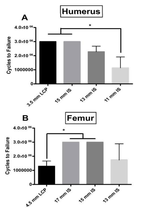
Humerus Dynamic Fatigue Testing: In the humerus model, for both the 15 mm IS construct and plate group all samples were intact after 3,000,000 cycles. The average number of cycles to failure for the 13 mm and 11 mm IS groups were 2,285,000 and 1,140,000 cycles respectively. There was no significant difference for cycles to failure between the LCP and the 15 mm and 13 mm IS constructs (Figure 6A). The 11 mm IS construct had significantly less cycles to failure than the LCP and 15 mm IS construct.
Femur Osteotomy
Femur Stiffness: For the femur model, the 17 mm IS construct group had the highest average stiffness (17 mm IS 1554 N/ mm, SD 178; LCP – 402.4 N/mm, SD 12.3; 15 mm IS 1510 N/mm, SD 271.4; 13 mm IS 1351 N/mm, SD 322.5). There was a significant difference in stiffness between the treatment groups (F=15.68, p value=0.001). The 13 mm, 15 mm, and 17 mm groups were not significantly different (Tukey’s Multiple Comparisons Test, p values>0.05). The LCP constructs were significantly less stiff than the IS constructs (17 mm vs. LCP, Mean Diff=1152 N/mm, p value=0.00155; 15 mm vs. Plate, Mean Diff=1107 N/mm, p value=0.002; 13 mm vs. LCP, Mean Diff=948.5, p value=0.0052) (Figure 4D).
Femur Peak and Yield Load: The 17 mm IS construct group had the highest average peak and yield load (4344 N, SD 591.1; 3035 N, SD 230.4 respectively). There was a significant difference in peak and yield load between the groups (F=16.2, p value=0.0009; F=10.41, p value=0.0039, respectively) (Figure 4E). The 17 mm IS construct had a significantly larger peak load when compared to all experimental groups (Tukey’s Multiple Comparisons Test, p values<0.05) (Figure 4E). The 17 mm IS construct also had the highest yield load, and this was significantly higher than the 13 mm IS experimental group and the LCP group groups (Tukey’s Multiple Comparisons Test, p values<0.05) (Figure 4F).
Femur Peak and Yield Displacement: The 4.5 mm LCP constructs had the highest peak and yield displacement (mean: 5.4 mm and 3.6 mm, respectively) of the construct groups. All groups tested had significantly different peak displacements except for the 17 mm and 15 mm IS constructs (Peak Displacement, 17 mm IS vs. LCP, Mean Diff=-2.467 mm, p value=0.0023; 15 mm IS vs. LCP, Mean Diff=-2.400 N, p value=0.0028; 13 mm IS vs. LCP, Mean Diff=-3.977, p value=<0.0001; 15 mm IS vs. 13 mm IS, Mean Diff=-1.577, p value=0.0300; 13 mm vs. 17 mm IS, Mean Diff=-1.510, p value=0.0370) (Figure 5C). Although the LCP construct group had the highest yield displacement, it was only significantly higher than the 13 mm IS construct group (Mean Diff=-2.653, p value=0.0222) (Figure 5D).
Femur Dynamic Fatigue Testing: For both the 17 mm and 15 mm IS constructs all samples were intact after 3,000,000 cycles. The average number of cycles to failure for the 13 mm IS and LCP groups were 1,733,000 and 1,297,000 cycles respectively. The 17 mm and 15 mm IS constructs withstood significantly higher cycles of fatigue testing compared to the LCP (p value=0.0052), but there was not a significant difference between the 13 mm IS construct and the 15 mm and 17 mm IS constructs (p values>0.05) (Figure 6B).
Figure 6: For the A) humerus group, the cumulative number of cycles to failure in three successive applied loads (33N for 1M cycles, 66N 1M cycles, 99N for 1M cycles). All plate and 15 mm samples were intact after 3,000,000 cycles (1M at 33N, 1M at 66N, 1M at 99N). Asterisk indicates a significant difference between the both the 15 mm IS and LCP groups and the 11 mm IS group. For the B) femur group the cumulative number of cycles to failure in three successive applied loads (689 N for 1M cycles, 798 N 1M cycles, 900 N for 1M cycles). All 17 mm and 15 mm IS samples were intact after 3,000,000 cycles (1M at 689 N, 1M at 798 N, 1M at 900 N). Asterisk indicates a significant difference between the both the 17 mm and 15 mm IS groups and the LCP group. The results from the LCP group are from the previously published Tompkins et al.15
DISCUSSION
The purpose of this study was to compare the biomechanical performance of three different diameters of the IS implant against a traditional metal plate fixation (LCP) system in both humerus and femur osteotomy defect models. We sought to determine whether an IS implant would perform in a biomechanically equivalent manner to the LCP for these indications. For the humerus osteotomy model, we have demonstrated that a 15 mm diameter IS implant exhibited comparable stiffness (11.67 vs. 9.983 N/mm), peak load (276.8 vs. 222.7 N), yield load (191.4 vs. 151.0 N), peak displacement (17.87 vs. 16.13 mm), yield displacement (31.9 vs. 30.92 mm), and cycles to failure (3,000,000 vs. 3,000,000) to the 3.5 mm LCP. These results show the 15 mm IS system had similar biomechanical performance to the 3.5 mm LCP across the parameters investigated, and this indicates that the two methods could have similar mechanical performance for the same clinical indication with the IS method offering the added benefit of a less invasive surgical procedure.
For the femur osteotomy model, have demonstrated that the 17 mm diameter IS implant exhibited significantly higher average stiffness (1554 vs. 402.4 N/mm), peak load (4344 vs. 1156 N), yield load (3035 vs. 1023 N), and cycles to failure (3,000,000 vs. 1,297,000) compared to the 4.5 mm LCP.15 The higher mechanical properties of the 17 mm IS suggests that the IS could have equivalent or increased mechanical performance in the clinical setting.
We acknowledge limitations to this investigation. A surrogate humerus and femur rather than a real human cadaver samples may be somewhat unrepresentative of clinical values because the surrogate bones are standardized. We believe this substitution was justified following published studies confirming the robust biomechanical performance of Sawbones constructs.21,25 The synthetic 4th generation Sawbones were developed using ASTM standards D-638 and D-695 to mimic the properties of bone, and have the added benefit of limiting variability found in cadaver samples.9,21,25,26 The 10 mm defect simulated may have been larger than is typically seen clinically, but provided a balance between isolating the implant sufficiently and avoiding the bone ends from coming into contact when flexed. Our decision to test for 3,000,000 cycles and up to 900 N of applied load may not have been sufficient to recapitulate the demands of the implant in vivo, but appears to have adequately captured the differences between the experimental groups, and was chosen based on estimates of repetitive loading during normal locomotion.23 We chose relatively small sample sizes for our experimental groups due to the fact that early pilot testing had shown large effect sizes.15,24 Lastly, the static and dynamic tests chosen may not fully represent the forces delivered during an in vivo situation. However, these tests were guided by the ASTM standards (F382-99) that are meant to ensure medical devices tested in vitro perform to clinical standards.22 Additionally, we submit that benchmarking the IS to the LCP implant, which is currently in clinical use, indicates that the two systems would perform similarly in a clinical environment with the added benefit of the IS implant able to offer a custom conforming fit. In a cadaver or live bone the internal geometry varies, and thus a conforming fit may serve as an advantage when compared to fixed diameter rods. This work compared conforming intramedullary rods to plates and screws and lays the foundation for additional comparisons to fixed-diameter intramedullary rods.
Large bone defects are a challenging clinical scenario that necessitate durable, reliable hardware fixation. Using biomechanical outcomes, this study compared the less invasive IS implant against a current clinical option (LCP) to determine if the novel IS would show similar performance. We hypothesized that equivalency could be found by testing various diameters of the IS implant. The 17 mm IS implant had significantly higher biomechanical performance when compared to the LCP system. The 15 mm and 13 mm IS implants were not consistently statistically superior, but for most parameters had higher values than the LCP system. This evidence coupled with clinical use, and in vivo data from a large animal model suggest that femur fixation by the IS will provide equivalent biomechanical properties to an LCP once implanted, with the added benefit that there will be less damage to adjacent tissue during implantation.7,8,20,27
ACKNOWLEDGMENTS
All authors contributed equally to this work. BRJ and AMB analyzed the data and wrote the manuscript. AMB and SCK designed and preformed experiments. RMT and CTB were responsible for study concept and critical revisions. The authors wish to acknowledge the staff of the Rhode Island Hospital Orthopedic Foundation for the assistance in completing this testing. The authors report IlluminOss, Inc. provided the test samples and funding for mechanical testing.